|
|
By: Neil E. Cotter |
Outreach |
|
|
2/3/12 |
Physics Circuits |
|
|
|
R in LED circuit wksheet |
|
|
|
|
|
|
|
|
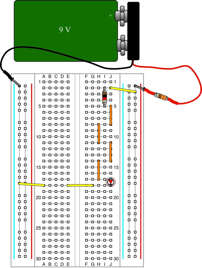
Lab: 1) Using your Outreach Kit, build the basic LED circuit, (see diagram below but leave out yellow meter or see the following URL: http://www.ece.utah.edu/eceCTools/_Outreach/Outreach_LED/Outreach_LEDVmeas.jpg) Once the LED lights up, move to step 2.
2) Set up a meter (shown in yellow in the diagram below) to measure voltage. Set up the meter as follows. First, make sure that the black probe for the meter is plugged into the input labeled COM or GND. This input is usually located in the lower right on the front of the meter. Second, make sure that the red probe for the meter is plugged into the input labeled V (along with other labels such as Ω). Third, to make the voltage measurement, turn the knob on the front of the meter to a position labeled with a voltage that is just larger than 9 V. For example, your meter might have a setting labeled 20 V or 40 V.
In the steps that follow, you will measure voltage drops across resistors and examine Ohm's law.
3) Measure the voltage across the resistor in each of the following circuits:
../Outreach_LED/R_LEDmeasVsmallbd.htm (one 1 kΩ resistor)
V Resistor =
../Outreach_LED/Rser_LEDmeasVsmallbd.htm (two 1 kΩ resistors in series)
V Series Resistors =
../Outreach_LED/Rpar_LEDmeasVsmallbd.htm (two 1 kΩ resistors in series)
V Parallel Resistors =
4) Set up a meter to measure current. Note: be certain when measuring current that there is always a resistor (in the circuit) that is in series with the meter. Set up the meter as follows. First, make sure that the black probe for the meter is plugged into the input labeled COM or GND. This input is usually located in the lower right on the front of the meter. Second, make sure that the red probe for the meter is plugged into the input labeled A or mA. Third, to make the current measurement, turn the knob on the front of the meter to a position labeled with a current that is just larger than 9 mA. For example, your meter might have a setting labeled 20 mA.
Measure the current through the resistor in each of the following circuits:
../Outreach_LED/R_LEDmeasIsmallbd.htm (one 1 kΩ resistor)
I Resistor =
../Outreach_LED/Rser_LEDmeasIsmallbd.htm (two 1 kΩ resistors in series)
I Series Resistors =
../Outreach_LED/Rpar_LEDmeasIsmallbd.htm (two 1 kΩ resistors in series)
I Parallel Resistors =
5) Ohm's law states that the voltage across a resistor is equal to the current, I, flowing through it times its resistance, R, in ohms.
![]()
Use the first current you measured (for a single resistor) and the nominal value of R = 1 kΩ for the resistor to calculate what the voltage across the resistor should be:
![]() =
=
Comment on how close the value is to the first voltage you measured in this lab.
6) Use your data and Ohm's law to determine the equivalent resistance for two 1 kΩ resistors in series and two resistors in parallel. Explain your work.
R series =
R parallel =
Fig. 1. Voltage measurement for one 1 kΩ resistor.
Fig. 2. Voltage measurement for two 1 kΩ resistors in series.
Fig. 3. Voltage measurement for two 1 kΩ resistors in parallel.
Fig. 4. Current measurement for one 1 kΩ resistor.
Fig. 5. Current measurement for two 1 kΩ resistors in series.
Fig. 6. Current measurement for two 1 kΩ resistors in parallel.