|
|
By: Neil E. Cotter |
Outreach |
|
|
2/20/12 |
Physics Circuits |
|
|
|
C in LED circuit wksheet |
|
|
|
|
|
|
|
|
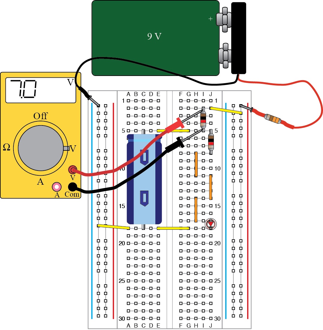
Lab: 1) Using your Outreach Kit, build the basic LED RC circuit but leave out the yellow meter (see Fig. 1 or see the following URL: http://www.ece.utah.edu/eceCTools/_Outreach/Outreach_LED/RC_LEDmeasVsmallbd.jpg) Note the indentation on the blue capacitor in the circuit. The capacitor must be inserted into the circuit in the correct direction (with indentation toward the top of the board) or the capacitor will be damaged.
Once the LED lights up, move to steps 2 and 3 where you will verify that you can determine the value of one capacitor from measurements and calculations.
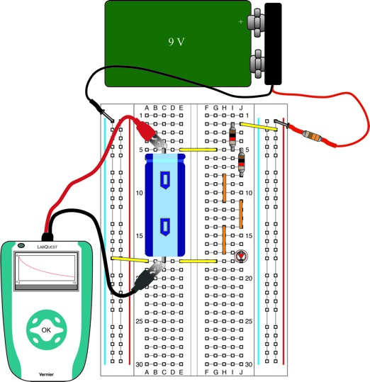
2) Set up a LabQuest data collection device as shown in Fig. 2 below to measure voltage across the capacitor. Remove the LED and replace it with a small red wire from your kit.
Measure the voltage across the capacitor as a function of time starting right after you unplug the red lead from the 9 V battery. Record the values of the voltage after 0 sec and 1 sec.
V Capacitor (0 sec) =
V Capacitor (1 sec) =
3) The following formula describes the capacitor voltage as a function of time:
![]()
where V0 is the starting voltage (in volts) on the capacitor, R is the resistance (1 kΩ), and C is the value of the capacitor in Farads
Using your data from part 3, determine the value of C. Show your work.
C =
Comment on how close your calculated value of C is to the value printed on the capacitor.
In the steps that follow, you will investigate the behavior of a circuit with two capacitors in series and with two capacitors in parallel.
4) Modify the circuit so that it has two capacitors in parallel. This means plugging in a second capacitor side-by-side with the first capacitor. This is achieved by plugging the indented end of the capacitor into row 5 and the other end into row 18. Use a LabQuest data collection device to measure voltage across the capacitor as a function of time starting right after you unplug the red lead from the 9 V battery. Note that, since the capacitors are in parallel, they have the same voltage across them. So we may measure the voltage across either capacitor.
Record the values of the capacitor voltage after 0 sec and 1 sec.
V Parallel C's (0 sec) =
V Parallel C's (1 sec) =
Using the same procedure as in part 3, determine the equivalent C value of the two C's in parallel. Show your work.
C|| =
According to theory, capacitances in parallel add.
![]()
Comment on how close your calculated value of total C is to the sum of the values printed on the capacitors.
5) Modify the circuit so that it has two capacitors in series. This means connecting the capacitors end-to-end so current goes through one capacitor and then the other. The leads at the ends of the capacitors connected in series must plug into row 5 and into row 18. Use a LabQuest data collection device to measure voltage across the entire series combination of capacitors as a function of time starting right after you unplug the red lead from the 9 V battery.
Record the values of the capacitor voltage after 0 sec and 1 sec.
V Parallel C's (0 sec) =
V Parallel C's (1 sec) =
Using the same procedure as in part 3, determine the equivalent C value of the two C's in series. Show your work.
Cs =
According to theory, capacitances in series combine as follows:
![]()
Comment on how close your calculated value of total C is to the value of Cs predicted by the above equation.
6) Using three capacitors, modify the circuit so that it has capacitors both in series and parallel. There are several configurations you might use. It is up to you to decide. Make a drawing of the configuration you use.
Use a LabQuest data collection device to measure voltage across the entire combination of capacitors as a function of time starting right after you unplug the red lead from the 9 V battery.
Record the values of the capacitor voltage after 0 sec and 1 sec.
V Parallel C's (0 sec) =
V Parallel C's (1 sec) =
Using the same procedure as in part 3, determine the equivalent C value of your configuration. Show your work.
Ceq =
Using the series and parallel formulae from above, calculated the predicted equivalent capacitance of your configuration:
Ceq predicted =
Comment on how close your calculated value of Ceq is to the value of Ceq predicted by the above equation.
Fig. 1. Circuit with capacitor, LED, and 1 kΩ resistors.
Fig. 2. Voltage measurement across C.