|
|
By: Neil E. Cotter |
Outreach |
|
|
2/7/12 |
Physics Circuits |
|
|
|
C in LED RC circuit wksheet |
|
|
|
|
|
|
|
|
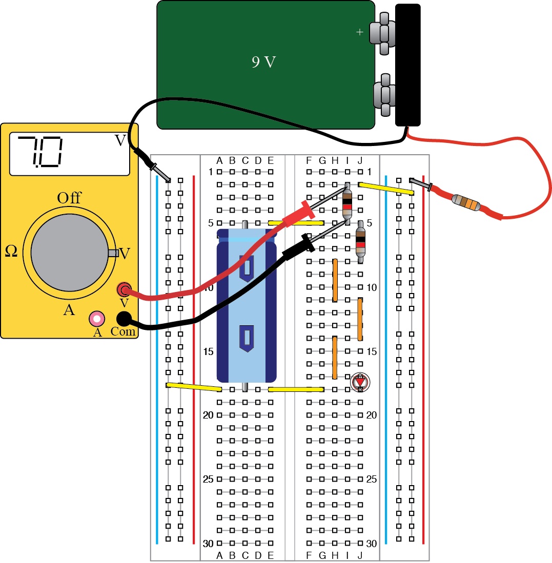
Lab: 1) Using your Outreach Kit, build the basic LED RC circuit, (see Fig. 1 but leave out yellow meter, or see the following URL: http://www.ece.utah.edu/eceCTools/_Outreach/Outreach_LED/RC_LEDmeasVsmallbd.jpg) Note the indentation on the blue capacitor in the circuit. The capacitor must be inserted into the circuit in the correct direction (with indentation toward the top of the board) or the capacitor will be damaged.
Once the LED lights up, move to step 2.
2) You will first make some qualitative observations about the RC circuit. The blue capacitor stores charge, much like a water tank, but it consists of parallel plates with an insulator between rolled up into a cylinder. Electrons collect on one plate and holes (missing electrons) collect on the other plate. The stored charge can supply power to the circuit, much like a battery, although the voltage on the capacitor drops as it supplies power and discharges electrons and holes.
Describe what the LED does when you disconnect the 9 V battery by pulling out the positive lead of the battery clip that is plugged into the upper right hand corner of the breadboard.
Describe what the LED does when you reconnect the 9 V battery by plugging the positive lead of the battery clip into the upper right hand corner of the breadboard.
Comment on what you think is happening to the current through the LED when you connect or disconnect the 9 V power to the circuit.
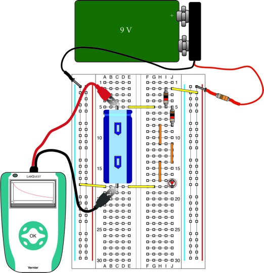
3) Now set up a LabQuest data collection device as shown in Fig. 2 below to measure voltage across the capacitor. Remove the LED and replace it with a small red wire from your kit.
Measure the voltage across the capacitor as a function of time starting right after you unplug the red lead from the 9 V battery. Record the values of the voltage after 1 sec, 2 sec, and 3 sec.
V Capacitor (1 sec) =
V Capacitor (2 sec) =
V Capacitor (3 sec) =
4) The following formula describes the capacitor voltage as a function of time:
![]()
where V0 is the starting voltage (in volts) on the capacitor, R is the resistance (1 kΩ), and C is the value of the capacitor in Farads
Using your data from part 3, determine the value of C. Explain your work.
C =
Comment on how close your calculated value of C is to the value printed on the capacitor.
Fig. 1. Circuit with capacitor, LED, and 1 kΩ resistors.
Fig. 2. Voltage measurement across C.